- Home Main page
- Company About us
- Product We offer
- Application Used to
- Technology Strength
- News Latest on us
- Contact Us Get in touch
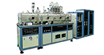
An "In-Line" PVD Sputtering System is one in which substrates pass linearly beneath one or more Sputter cathodes to acquire their Thin Film coating. Normally the substrates are loaded onto a carrier or pallet in order to facilitate this motion, and some smaller systems handle just one pallet per batch run. Larger systems may have the capability of handling multiple pallets through the use of end station pallet handlers that send and receive one pallet after another in a continuing convoy passing through the transport subsystem, the tip of each following behind the tail of the prior one.
The most common, and least complex, configuration is to have the pallets and cathodes horizontal with cathodes on top and substrates on the bottom in a sputter down orientation. In this mode, gravity is usually the only thing holding the substrates onto the pallets, and also the only thing holding the pallets onto the transport mechanism, which can just be chains running along side rails through the vacuum chamber.
That horizontal arrangement can also be done with cathodes on the bottom and substrates on top for a sputter up orientation, but obviously this complicates the tooling somewhat, now requiring mechanical means of keeping the substrates in place so they do not fall. For single sided coating, this is not a very common configuration, but it is sometimes done for double sided coating, with cathodes both above and below the pallets. The pallets in this case have appropriate openings to hold the substrates so that the bottom sides can receive the sputter up coating from the lower cathode at the same time the top side gets the sputter down coating from the upper cathode.
But horizontal does have a disadvantage in terms of particulates. In sputter down mode, particles that get generated inside the chamber can easily land on the substrates and get embedded in the film - and that is bound to occur. Deposition systems are somewhat self contaminating with material getting places other than just on the substrates. The biggest routine maintenance issue is keeping things clean. In sputter up orientation, those particles do not get on the substrates, but can land on the targets and get re-sputtered.Paper aluminum thin films vacuum coating machine
So for a better particulate environment, there is also the vertical orientation option for side sputtering. Both the cathodes and the pallets are vertical, and deposition is lateral. The tooling and transport system become substantially more complex to keep the substrates on the pallet and also handle the pallet in that orientation, but particles are much less likely to fall onto either the cathode or the substrate.
In any of these configurations, all of the various types of cathodes can be used, with Magnetrons generally being the most popular, either planar or inset. And power can be any of the various types available such as RF, MFAC, DC, or pulsed DC as desired for the application. Optional stages such as Sputter Etch, Heat, or Ion Sources can also be accommodated, and the full array of instrumentation and controls are available for metallic/conductive coatings, dielectrics, optical coatings or other sputter applications.
Although it is possible to use other types, most of the cathodes in such systems are rectangular. As a rule, the long axis of the rectangular cathode is across the chamber and the short axis is along the direction of pallet travel. And, although it is possible to configure cathodes for intentionally non uniform coating, the great majority of users want their substrates to be uniformly coated. In an in-line system as we are discussing, the uniformity in the direction of pallet travel is dependent on the stability of the cathode power and chamber pressure/gas mixture, along with the stability of the transport speed, and finally the start/stop positions in front of and behind the deposition zone.
For a single pallet, or for the first and last pallet in a tip to tail continuous run, the start position (as well as the stop position) must be far enough out from directly under the target to avoid accruing unplanned deposition during any pre-sputter stabilization period, prior to starting the scan. Any starts, stops, or reversals of scan direction should take place outside the actual deposition zone and the scan should be steady and uninterrupted through the deposition zone. Scans can be single pass in either direction, or can be back and forth to build up thicker coatings.
Three and four target systems are quite common, and the chamber length can be increased to accommodate additional sources as required. With enough power supplies, multiple targets can be simultaneously used in a single pass. With different target materials on the cathodes, multiple layers can thus be deposited in a single pass, or with duplicate targets, thicker coatings can be achieved in a single pass.
Uniformity in the other axis, perpendicular to the pallet scan direction, is determined by the performance of the cathode, including, especially for reactive sputtering, possible gas distribution issues. With Magnetrons, the placement and strength of the magnets can affect both target utilization and inherent uniformity, and there is normally a trade off between those two aspects. Along the center of the target's length, both uniformity and utilization are normally quite good, but at the ends, where the "race track" erosion path turns around, the deposition rate and resulting film thickness will drop off unless magnets are adjusted to compensate, but if that is done the erosion channel gets deeper there and that reduces target utilization (the percentage of the total target mass that can be sputtered off before the deepest erosion point breaks through to the backing plate).
Tip to tail processing in the larger multi pallet systems is also quite beneficial for target material utilization in terms of getting more on your substrates and less on shields and other chamber parts. In a single pallet system, the lead pallet is the only pallet, and as it is leaving the deposition zone, it must continue to scan until the trailing edge - the tail - is all the way out, with the target still burning the whole time, which effectively wastes some of the target material.
In the tip to tail approach, there is only a short gap between one tail and the next tip and then material is once again going onto a "live" pallet full of substrates, with a new pallet entering as the leading pallet exits the deposition zone There are many variables that can affect this number, but as a rule of thumb the tip to tail approach can be nearly twice as efficient in material usage as the single pallet.
At the high end of versatility, the addition of slit valves to isolate process sections, combined with sophisticated automation control, can make it possible to operate different sections simultaneously with different gas environments (pressure and gas mixture), perhaps direct sputtering one layer on a pallet in section one, while simultaneously reactively sputtering a different layer on another pallet in a separate isolated section. In-Line sputter systems can be customized to accommodate a wide range of process requirements and substrate sizes.
No. 79 West Jinniu Road,
Yuyao,
Ningbo City, Zhejiang Provice, China
+86-13486478562

Copyright © Ningbo Danko Vacuum Technology Co., Ltd All Rights Reserved.
China PVD Coating Machines Manufacturers


 Español
 Português