Summary:1 sputtering variable
1.1 Voltage and Power
If the applied voltage is changed within the pressure ra...
1.1 Voltage and Power
If the applied voltage is changed within the pressure range where the gas can be ionized, the impedance of the plasma in the circuit will change accordingly, causing the current in the gas to change. Changing the current in the gas can create more or fewer ions that hit the target to control the sputtering rate.
In general: increasing the voltage increases the ionization rate. This will increase the current, so it will cause a drop in impedance. When the voltage is increased, the decrease in impedance will greatly increase the current, that is, the power will be greatly increased. If the gas pressure is constant and the speed at which the substrate moves under the sputtering source is constant, then the amount of material deposited on the substrate is determined by the power applied to the circuit. In the range used in VONARDENNE coated products, there is a linear relationship between power increase and sputter rate increase.
1.2 Gas environment
The vacuum system and the process gas system together control the gas environment.
First, a vacuum pump draws the chamber body to a high vacuum (approximately 10-torr). The process gas is then charged by the process gas system (including pressure and flow control regulators) to reduce the gas pressure to approximately 2X10⁻³torr. To ensure the proper quality of the same film, the process gas must be 99.995% pure. In reactive sputtering, mixing a small amount of an inert gas (eg, argon) in the reactive gas can increase the sputtering rate.
1.3 Gas pressure
Reducing the gas pressure to a certain point increases the mean free path of the ions, which in turn allows more ions to strike the cathode with enough energy to bombard the particles out, ie increase the sputtering rate. Beyond this point, the amount of ionization decreases due to too few molecules participating in the collision, resulting in a decrease in the sputtering rate. If the gas pressure is too low, the plasma is extinguished and sputtering stops. Increasing the gas pressure increases the ionization rate, but also reduces the mean free path of the sputtered atoms, which also reduces the sputtering rate. The gas pressure range over which the maximum deposition rate can be obtained is very narrow. If reactive sputtering is being performed, since it is continuously consumed, new reactive sputtering must be replenished at an appropriate rate in order to maintain a uniform deposition rate.
1.4 Transmission speed
The movement of the glass substrate under the cathode is carried out by means of a drive. The low drive speed allows the glass to pass longer in the cathode range, which allows for thicker layers to be deposited. However, in order to ensure the uniformity of the film layer, the transmission speed must be kept constant.
Typical transmission speeds in the coating area range from 0 to 600 inches per minute (approximately 0 to 15.24 meters). The typical operating range is between 90 to 400 inches per minute (approximately 2.286 to 10.16 meters), depending on the coating material, power, number of cathodes, and type of coating.
1.5 Distance and speed and adhesion
For maximum deposition rate and improved film adhesion, the substrate should be placed as close to the cathode as possible without damaging the glow discharge itself. The mean free paths of sputtered particles and gas molecules (and ions) also play a role. As the distance between the substrate and the cathode increases, the probability of collisions increases, so that the ability of the sputtered particles to reach the substrate decreases. Therefore, for maximum deposition rate and best adhesion, the substrate must be placed as close to the cathode as possible.
2 system parameters
The process is affected by many parameters. Some of them can be changed and controlled during process operation; while others, although fixed, can generally be controlled within a certain range before process operation. Two important fixed parameters are: target structure and magnetic field.
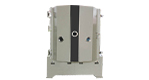
2.1 Target structure
Each individual target has its own internal structure and particle orientation. Due to differences in internal structure, two targets that appear to be identical may exhibit vastly different sputtering rates. This should be especially noted in coating operations where new or different targets are used. If all target blocks have a similar structure during processing, adjusting the power supply, increasing or decreasing the power as needed, can compensate for it. Within a set of targets, different sputtering rates are also produced due to different particle structures. The machining process can cause differences in the internal structure of the target, so even targets of the same alloy composition will have differences in sputtering rates.
Likewise, parameters such as the crystal structure, grain structure, hardness, stress, and impurities of the target block can affect the sputtering rate, which can result in streak-like defects on the product. This also requires attention during coating. However, this situation can only be resolved by replacing the target.
The target depletion zone itself also causes relatively low sputtering rates. At this time, in order to obtain a good film layer, the power or transmission speed must be readjusted. Because speed is critical to a product, the standard and appropriate adjustment is to increase power.
2.2 Magnetic field
The magnetic field used to trap the secondary electrons must be consistent across the target surface and the magnetic field strength should be appropriate. Non-uniform magnetic fields produce non-uniform layers. If the magnetic field strength is not appropriate (eg too low), then even the same magnetic field strength will result in slow film deposition rates and possible sputtering at the bolt head. This can contaminate the membrane. If the magnetic field strength is too high, the deposition rate may be very high at the beginning, but this rate will quickly drop to a very low level due to the etched area. Likewise, this etched area also results in a lower target utilization rate.
2.3 Variable parameters
During the sputtering process, dynamic control of the process can be performed by changing these parameters. These variable parameters include: power, speed, type of gas and pressure.
3.1 Power
Each cathode has its own power source. Depending on the size of the cathode and system design, the power can vary from 0 to 150KW (nominal). The power supply is a constant current source. In the power control mode, the power is fixed while the voltage is monitored, and the constant power is maintained by changing the output current. In current control mode, the output current is fixed and monitored, while the voltage can be adjusted. The higher the power applied, the greater the deposition rate.
3.2 Speed
Another variable is speed. For single-ended coaters, the transmission speed of the coating zone can be selected from 0 to 600 inches per minute (approximately 0 to 15.24 meters). For double-ended coaters, the transmission speed of the coating zone can be selected from 0 to 200 inches per minute (approximately 0 to 5.08 meters). At a given sputtering rate, lower drive speeds indicate thicker films deposited.
3.3 Gas
The last variable is gas. Two of the three gases can be selected for use as the main gas and the auxiliary gas. Between them, the ratio of any two can also be adjusted. Gas pressure can be controlled between 1 ~ 5X 10⁻³torr.
3.4 Relationship between cathode/substrate


 Español
 Português